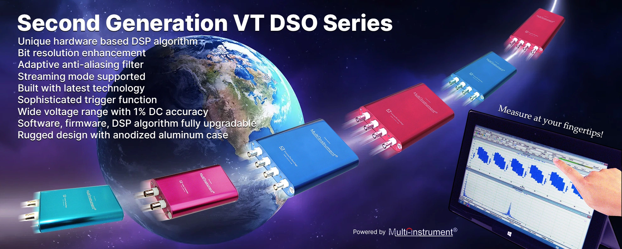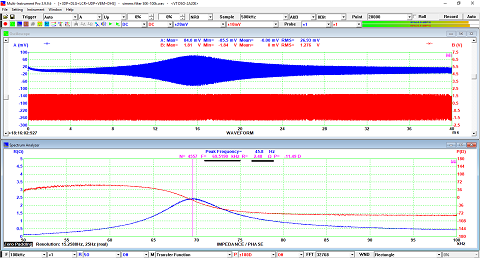

The second-generation VT DSOs (Multi-Function PC USB oscilloscopes) feature Virtins Technology's unique hardware-based DSP algorithm which enhances the performance and functionality dramatically without adding extra hardware cost. When used in conjunction with Multi-Instrument software, these VT DSOs convert any desktop, laptop, or tablet PC into a powerful oscilloscope, spectrum analyzer, multimeter, data logger, signal generator and so forth, all of which work simultaneously.
Compared with the first-generation VT DSOs and those USB Oscilloscopes from other manufacturers, this new generation has the following major advantages:
As the sampling rate goes down, the bit resolution of the ADC goes up. It is possible to achieve a bit depth of 16 with the second-generation VT DSOs. The increase in bit resolution is
accompanied by a decrease in noise level, resulting in an increase in dynamic range and measurement accuracy.
Article: Bit Resolution Enhancement

Beside the normal frame mode, the second-generation VT DSOs support streaming mode as well in Oscilloscope. Unlike the normal frame mode, under which the record length is limited by the hardware's buffer size, streaming mode uses the huge space available in the computer, either on hard disk or in memory, to record data continuously. This breaks through the limitation imposed by the DSOs' buffer and thus greatly extends the maximum record length.
Digital trigger has much better level and timing accuracy than analog trigger. Its trigger level accuracy is 1 count of the ADC and timing accuracy is equal to the sampling interval. Moreover, the second-generation VT DSOs are equipped with hardware based digital filters which are able to filter out noises and / or high frequencies in real time, ensuring stable triggering under all conditions.

This mode allows hundreds of consecutive waveforms to be superimposed / drawn in the oscilloscope window in three ways: Phosphorescent, Rainbow, Equivalent Time Sampling. The former two are useful to capture intermittent and unstable events hidden in a series of repeated normal events, while the latter one can be used to increase the displayed samples per cycle when the real time samples per cycle is insufficient to render the actual waveform properly, provided that the signal itself is repetitive.
The external trigger input channel of a second-generation VT DSO can be used as a digital input channel. It is actually a 1-bit ADC with the threshold for digitization adjustable. With two analog input channels and one digital input channel, the oscilloscope can be used for mixed signal measurements.
The USB DSOs in the market are generally equipped with only one fixed anti-aliasing filter for the highest sampling frequency. Aliasing will still occur when the sampling frequency goes down.
This will cause wrong measurements in both the oscilloscope and the spectrum analyzer. The second-generation VT DSOs solve this problem using anti-aliasing filters that can adapt to the
sampling frequency.
Article: Adaptive Anti-Aliasing Filter
The signal generator of a second-generation VT DSO supports both streaming and DDS (Direct Digital Synthesis) modes. Complicated signals such as white noise, MLS, frequency sweep and amplitude sweep, which generally are not found in other USB signal generators in the market, can be generated using the second-generation VT DSOs, for both streaming and DDS modes. While consuming more CPU time, streaming mode provides more functionality than DDS mode.
The signal generator of a second-generation VT DSO supports DDS interpolation which, in effect, increases the DDS buffer in the hardware by a factor of 65536.
The oscilloscope and signal generator of a second-generation VT DSO can work simultaneously. You can generate a stimulus to the Device Under Test (DUT) and acquire the response from that device at the same time. You can even configure a sequence of steps to generate different stimuli to the DUT and analyze the different responses from it.
All the second-generation VT DSOs are individually calibrated to the specifications. This results in higher accuracy than their peers without additional cost. Some models allow the user to re-calibrate them.
| Model | ADC (Oscilloscope) | DI | DAC (Signal Generator) | |||||||||||
|---|---|---|---|---|---|---|---|---|---|---|---|---|---|---|
| AI | Band Width (MHz) | Max. Sampling (MSPS) | Bit Depth (Bits) | Buffer* (Bytes) | Full Scale Range (V) | EXT as DI | Full Scale Range (V) | AO | Band Width (MHz) | Max. Sampling (MSPS) | Bit Depth (Bits) | DDS Buffer* (Bytes) | Full Scale Range (V) | |
| 2810 | 2 | 40 | 100 | 8~16 | 40000 | ±0.01 ~ ±50 | Y | ±20 | 1 | 0.15 | 3.125 | 10 | 2048 | ±2 |
| 2810R | 2 | 40 | 100 | 8~16 | 40000 | ±0.05 ~ ±50 | ||||||||
| 2810E | 2 | 40 | 100 | 8~16 | 40000 | ±0.01 ~ ±50 | Y | ±20 | 1 | 60 | 200 | 10 | 2048 | ±2 |
| 2820 | 2 | 80 | 200 | 8~16 | 40000 | ±0.01 ~ ±50 | Y | ±20 | 1 | 0.15 | 6.25 | 10 | 2048 | ±2 |
| 2820R | 2 | 80 | 200 | 8~16 | 40000 | ±0.05 ~ ±50 | ||||||||
| 2820E | 2 | 80 | 200 | 8~16 | 40000 | ±0.01 ~ ±50 | Y | ±20 | 1 | 60 | 200 | 10 | 2048 | ±2 |
| 2A10 | 2 | 40 | 100 | 10~16 | 40000 | ±0.01 ~ ±50 | Y | ±20 | 1 | 0.15 | 3.125 | 12 | 2048 | ±2 |
| 2A20 | 2 | 80 | 200 | 10~16 | 40000 | ±0.01 ~ ±50 | Y | ±20 | 1 | 0.15 | 6.25 | 12 | 2048 | ±2 |
| 2A10E | 2 | 40 | 100 | 10~16 | 40000 | ±0.01 ~ ±50 | Y | ±20 | 1 | 60 | 200 | 12 | 2048 | ±2 |
| 2A20E | 2 | 80 | 200 | 10~16 | 40000 | ±0.01 ~ ±50 | Y | ±20 | 1 | 60 | 200 | 12 | 2048 | ±2 |
*Buffer size for streaming mode is unlimited. DDS buffer size is increased by a factor of 65536 under DDS interpolation mode.
| Model | ADC (Oscilloscope) | DI | DAC (Signal Generator) | |||||||||||
|---|---|---|---|---|---|---|---|---|---|---|---|---|---|---|
| AI | Band Width (MHz) | Max. Sampling (MSPS) | Bit Depth (Bits) | Buffer (Bytes) | Full Scale Range (V) | EXT as DI | Full Scale Range (V) | AO | Band Width (MHz) | Max. Sampling (MSPS) | Bit Depth (Bits) | DDS Buffer (Bytes) | Full Scale Range (V) | |
| 2810H | 2 | 40 | 100 | 8 | 60000 | ±0.05 ~ ±20 | N | ±4 | ||||||
| 2815H | 2 | 60 | 150 | 8 | 60000 | ±0.05 ~ ±20 | N | ±4 | ||||||


