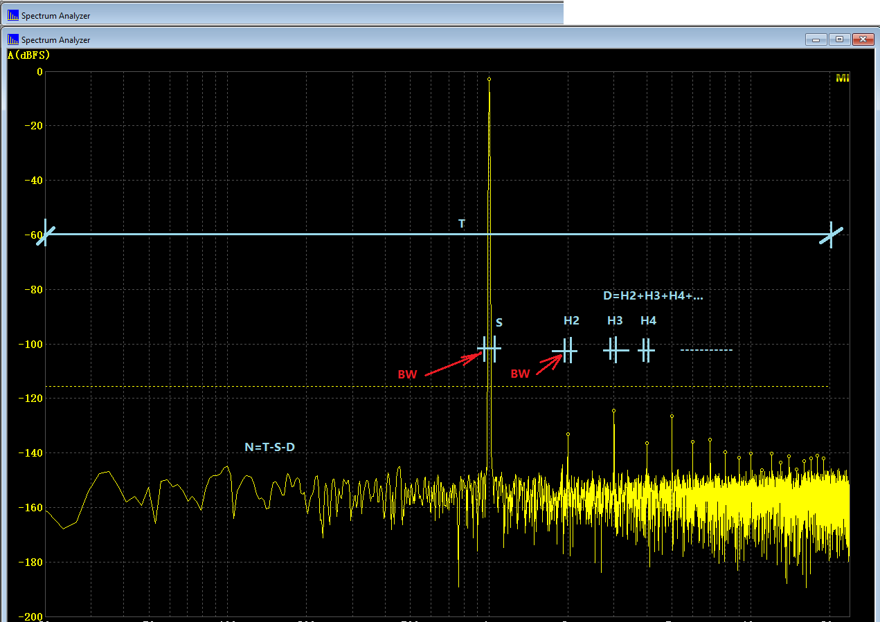
The total power (T) of the signal consists of three parts: fundamental of the signal (S), harmonic distortion (D=H2+H3+H4+...), noises (N), i.e. T = S + D + N. THD, THD+N, SNR, SINAD, NL are derived based on the measurement of these three parts. T can be readily calculated by summing up the power in all FFT bins in the specified frequency range of interest (e.g. 20Hz~20kHz). The power of a sinusoidal component (e.g. S, H2, H3, H4…) can be calculated from a few FFT bins around its peak (See figure below).

- THDcalculation.png (43.52 KiB) Viewed 253778 times
The bandwidth (BW) that is used to calculate the power of a sinusoidal component reduces as FFT frequency resolution increases. As a result, the measurement accuracy increases. The BW is usually software algorithm dependent. The following two examples illustrate how BW can be selected and its impact on S,D and N calculation.
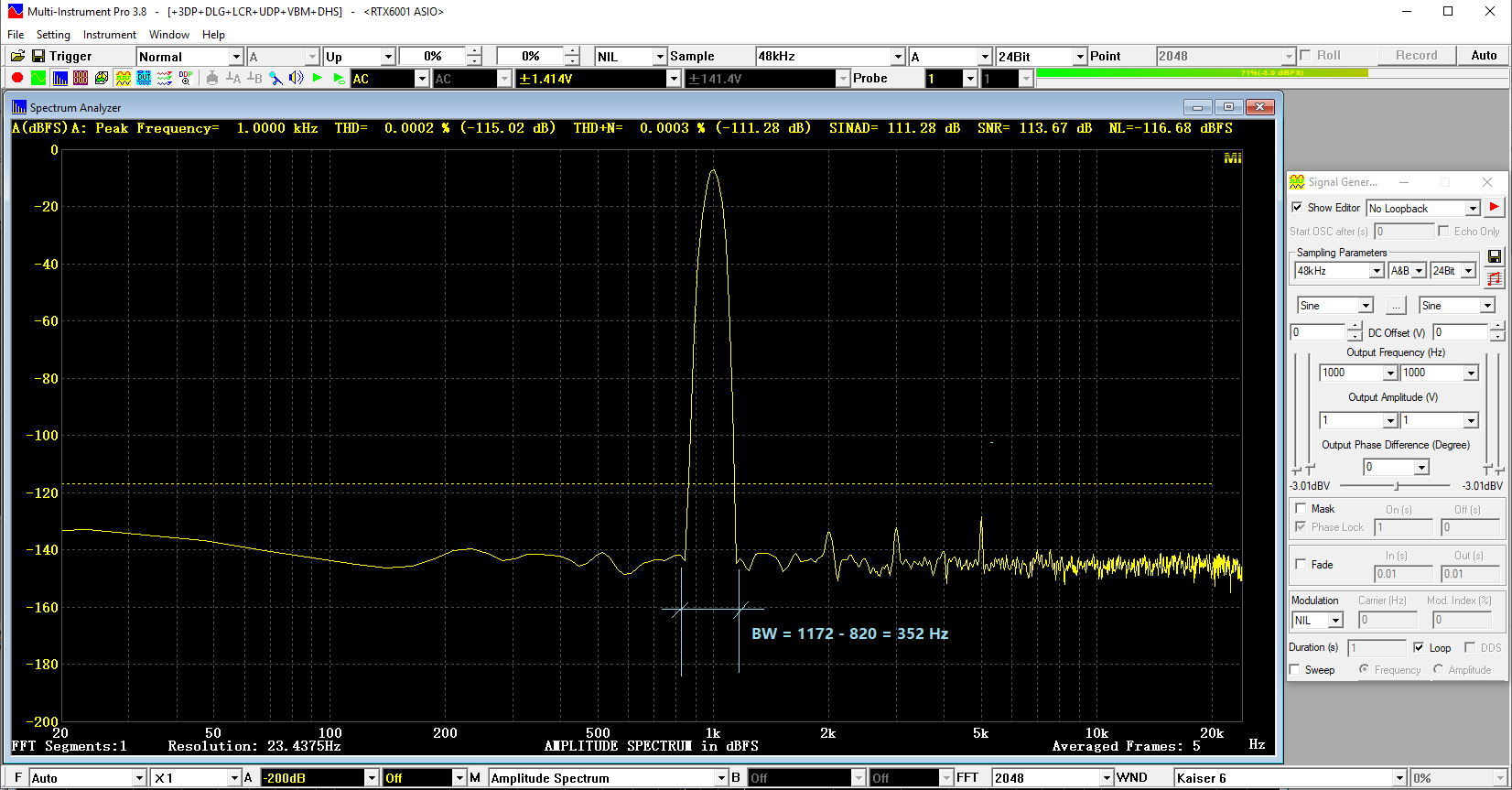
1. [FFT Size] = 2048, [Frequency Resolution] = 23Hz
THD = -115.02dB, THD+N = -111.28dB, SINAD = 111.28 dB, SNR =113.67dB, NL = -116.68 dBFS

- FFT=2048-BW.png (84.78 KiB) Viewed 253778 times
The BW in this case is 1172Hz-820Hz=352 Hz which can be clearly seen from the width of the fundamental peak. This is pretty coarse as the noise that falls into this BW will be falsely taken as a part of the fundamental or harmonic power.
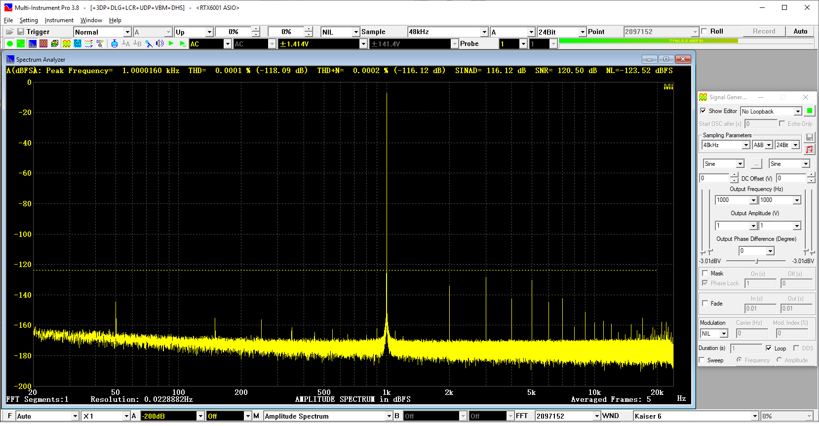
2. [FFT Size] = 2097152, [Frequency Resolution] = 0.023Hz
THD = -118.09dB, THD+N = -116.12dB, SINAD = 116.12 dB, SNR =120.50dB, NL = -123.52 dBFS

- FFT=2097152-BW.png (85.71 KiB) Viewed 253778 times
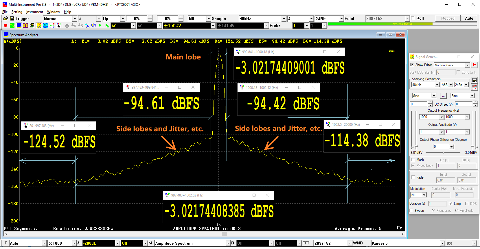
The BW in this case is 1002.52Hz – 997.483Hz = 5Hz. The corresponding S=-3.02174408385 dBFS, as shown in the close-up of the fundamental peak.

- FFT=2097152-BW-CloseUp.png (95.97 KiB) Viewed 253778 times
Now, if we use Kaiser 6’s main lobe width BW =1000.18Hz - 999.841Hz=0.339 Hz for the fundamental power calculation instead, then S=-3.02174409001 dBFS. The difference between the two methods is negligibly small (only 0.00000000616 dBFS) for the fundamental power calculation. However, this will cause big difference in noise level calculation, because the power levels in the frequency bands 997.483Hz ~ 999.841 Hz and 1000.18Hz ~ 1002.52Hz are -94.61dBFS and -94.42 dBFS respectively, much higher than the measured noise level -123.52 dBFS.
In other words, a slightly-narrower-than-proper BW can falsely increase the noise level significantly. On the other hand, due to the nearly uniform distribution of noises, a slightly-wider-than-proper BW will be on the safer side and has minimum impact on the results. The picture also shows the power level in the frequency bands 20 Hz ~ 997.483 Hz and 1002.5Hz~20000Hz are -124.52 dBFS and -114.38 dBFS (note: this one contains both noise and harmonic distortion in this frequency band) respectively. The above power levels are calculated using [Spectrum Analyzer Processing]>"Energy in User Defined Frequency Bands" in MI.
The noise level difference in the above two examples is -116.68 dBFS - 123.52 dBFS = 6.84 dBFS. if you want Example 2 to measure the same noise level as Example 1, then the BW have to be reduced, which does not look correct from the spectrum, especially when a much wider BW is actually used in Example 1.
The skirts of the harmonics are usually buried under the noise floor and thus do not account for the above noise level difference.
In summary, the measurement accuracy will be improved with a larger FFT size, because the larger the FFT size, the higher the frequency resolution, the narrower the BW required, the better segregation of S, D and N. Whether the improved measurement accuracy will lead to better or worse audio parameters depends on the spectrum details, in particular the skirt of the fundamental.
