PC USB 24-bit dual-channel 48 kSPS 0.03Hz~23kHz
IEPE Data Acquisition Interface
Manual 
US$399.95
Free Express Shipping
| VT IEPE-2G05 |
VT IEPE-2G05A |
VT IEPE-2G05B |
|
|
|
|
| VT IEPE-2G05C |
VT IEPE-2G05D |
VT IEPE-2G05E |
|
|
|
|
Download and try the fully functional Multi-Instrument software using your sound card as the ADC and DAC device!
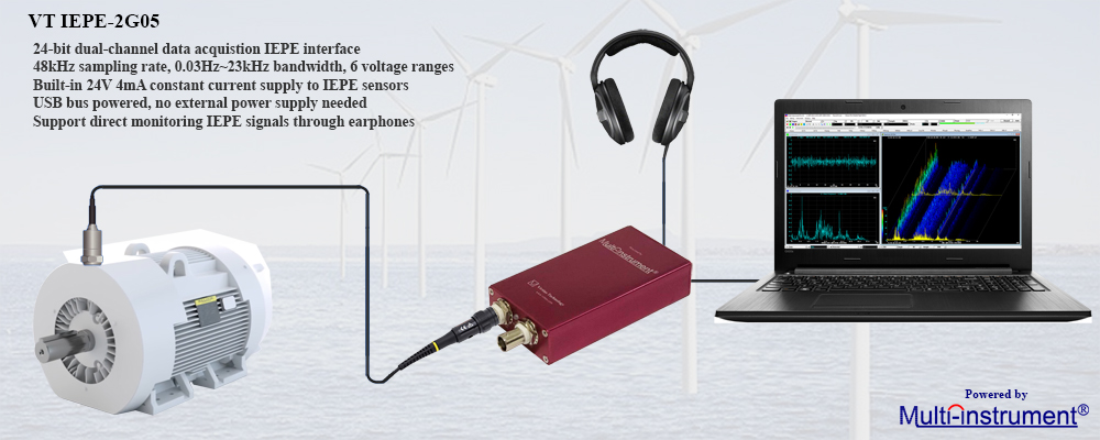
1. Instroduction
VT IEPE-2G05 is a 24-bit, dual-channel, USB data acquisition
interface specially designed for use with IEPE sensors such as
IEPE accelerometers, IEPE microphones and IEPE hydrophones. Each
channel has six calibrated voltage measurement ranges for easy
calibration to sensor sensitivity: ± 250 mV, ± 500 mV, ± 1 V, ±
2.5 V, ± 5 V, ± 10 V, and a built-in 24V 4mA current source to
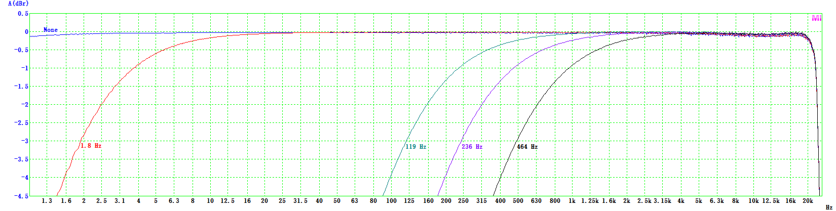
drive an IEPE sensor directly. It contains a hardware high pass
filter with 5 selectable -3dB corner frequencies: None (0.03Hz),
1.8 Hz, 119 Hz, 236 Hz, 464 Hz. The signals sensed by the IEPE
sensors can be amplified and output directly from the stereo
headphone jack even without running the PC software. When
used in conjunction with the Multi-Instrument®
software, the setup allows you to take reliable and quality
vibration measurements as simply as plug & play. No external
power supply and driver installation is required. It is a truly
hassle-free portable
noise and vibration measurement solution.
VT IEPE-2G05A has the same specifications as VT IEPE-2G05, except that its Channel B has a 20 dB higher analog gain, with its voltage measurement ranges changed to: ± 25 mV, ± 50 mV, ± 100 mV, ± 250 mV, ± 500 mV, ± 1 V. The increased gain makes it more capable of measuring low level signals such as a low-dBSPL sound.
|
|
VT IEPE-2G05B has the same specifications as VT IEPE-2G05, except that its two input channels A & B have a 20 dB higher analog gain, with their voltage measurement ranges changed to: ± 25 mV, ± 50 mV, ± 100 mV, ± 250 mV, ± 500 mV, ± 1 V. The increased gain makes it more capable of measuring low level signals such as a low-dBSPL sound.
VT IEPE-2G05C/D/E have the same specifications as VT IEPE-2G05, except that their Channels B have a 40 dB higher analog gain, with their voltage measurement ranges changed to: ± 2.5 mV, ± 5 mV, ± 10 mV, ± 25 mV, ± 50 mV, ± 100 mV. The increased gain makes them more capable of measuring extra low-dBSPL sound. Their Channels A have a 0dB /20dB / 40dB higher analog gain respectively than that of VT IEPE-2G05.
All the above models can be switched to a voltage measurement mode (e.g. for the purpose of accepting the voltage pulses output by a
non-IEPE tachometer) by cutting off the 24V 4mA constant current supply through an internal DIP switch in each channel. The 4mA constant driving current can be modified as well (e.g. for the purpose of driving a very long cable). These customizations are recommended to be done in the factory upon request before shipping.
It is possible to run multiple VT IEPE-2G05/A/B/C/D/E using multiple instances of the software on the same computer.
2. Package Contents
1) VT IEPE-2G05/A/B/C/D/E unit with a hardware
activated Multi-Instrument Standard
software license
2) USB cable (1.5 m)
3) CD (contains the
copy-protected Multi-Instrument Software)
4) Carrying case
3. Optional Items
You may follow the links below to purchase the optional items:
1)
IEPE Accelerometers,
IEPE Velocity Sensors,
IEPE Impedance Heads,
IEPE Impact Hammers (including
a mounting stud / screw and a cable from sensor to BNC, default: 2m)
2)
IEPE Measurement Microphones
(including a small mic stand, a mic clip and a cable from mic to BNC,
default: 2m)
3) IEPE
Measurement Hydrophones
4)
Magnetic Mounting Bases
5) Software License
Upgrades
6) USB Isolators
7) IEPE simulators
Note: It is usually possible to place the
optional items inside the same carrying case with VT IEPE-2G05/A/B/C/D/E.
4.
Hardware Specifications
| Number of Input Channels |
2 |
| Sampling Frequency |
48 kHz (original), 44.1
kHz, 32 kHz, 22.05 kHz, 16 kHz, 11.025 kHz, 8 kHz, 4 kHz, 2 kHz
... |
| ADC Bit Resolution |
24 Bits (can be reduced to
16 bits or 8 bits) |
| Input Voltage Ranges |
IEPE-2G05: ± 250 mV, ± 500 mV, ± 1 V,
± 2.5 V, ± 5 V, ± 10 V
IEPE-2G05A:
Ch.A: ± 250 mV, ±
500 mV, ± 1 V, ± 2.5 V, ± 5 V, ± 10 V
Ch.B: ± 25 mV, ± 50 mV,
± 100 mV, ± 250 mV, ± 500 mV, ± 1 V
IEPE-2G05B:
± 25
mV, ± 50 mV, ± 100 mV, ± 250 mV, ± 500 mV, ± 1 V
IEPE-2G05C:
Ch.A: ± 250 mV, ± 500 mV, ± 1 V, ± 2.5 V, ± 5 V, ± 10 V
Ch.B: ±2.5 mV, ±5 mV, ±10 mV, ±25 mV, ±50 mV, ± 100 mV
IEPE-2G05D:
Ch.A: ± 25 mV, ± 50 mV, ± 100 mV, ± 250 mV, ± 500 mV,
± 1V
Ch.B: ± 2.5 mV, ± 5 mV, ± 10 mV, ± 25 mV, ± 50 mV, ± 100 mV
IEPE-2G05E:
± 2.5 mV, ± 5 mV, ± 10 mV, ± 25 mV, ± 50 mV, ± 100
mV |
| Input Connectors &
Interface |
BNC, Single Ended, IEPE,
24V 4mA |
| Input Coupling Type |
IEPE-2G05: AC (High pass filtered at
0.03Hz)
IEPE-2G05A:
Ch.A: AC (High pass filtered at
0.03Hz)
Ch.B: AC (High pass filtered at 0.3Hz)
IEPE-2G05B: AC (High pass filtered at 0.3Hz)
IEPE-2G05C:
Ch.A: AC (High pass filtered at 0.03 Hz)
Ch.B: AC (High pass filtered at 3 Hz)
IEPE-2G05D:
Ch.A: AC (High pass filtered at 0.3 Hz)
Ch.B: AC (High pass filtered at 3 Hz)
IEPE-2G05E: AC (High pass filtered at 3 Hz) |
| Input Isolation |
No (Isolation can be
achieved through a USB isolator) |
| Input Impedance |
IEPE-2G05: 510 kΩ
IEPE-2G05A:
Ch.A: 510 kΩ
Ch.B: 51 kΩ
IEPE-2G05B:
51 kΩ
IEPE-2G05C:
Ch.A: 510 kΩ
Ch.B: 5.1 kΩ
IEPE-2G05D:
Ch.A: 51 kΩ
Ch.B: 5.1 kΩ
IEPE-2G05E: 5.1 kΩ |
| Input High Pass Filter |
None, 1.8 Hz, 119 Hz, 236
Hz, 464 Hz |
| Frequency Response |
IEPE-2G05: 0.03 Hz ~ 22.8 kHz
IEPE-2G05A:
Ch.A: 0.03 Hz ~ 22.8 kHz
Ch. B: 0.3 Hz ~
22.8 kHz
IEPE-2G05B: 0.3 Hz ~ 22.8 kHz
IEPE-2G05C:
Ch.A: 0.03 Hz~22.8kHz
Ch.B: 3 Hz~22.8kHz
IEPE-2G05D:
Ch.A: 0.3 Hz~22.8kHz
Ch.B: 3 Hz~22.8kHz
IEPE-2G05E:
3 Hz~22.8kHz |
| Frequency Accuracy |
50 PPM |
| Anti-aliasing Filter |
22.8 kHz at Sampling Rate
48 kHz, proportionally adaptive to Sampling Rate Chosen |
| Buffer Size |
Virtually unlimited
(streaming mode) |
| Voltage Accuracy |
±0.5% at 1 kHz |
| Output Connector &
Interface |
ϕ3.5 mm Stereo Audio Jack |
| Output Voltage Range |
±0.5 V |
| Digital Input / Output
Standard |
USB Audio Class 1 |
|
Calibration |
Individually done at factory, user re-calibratable |
| PC Interface |
USB 2.0 Full Speed / USB
1.1 |
| Device Category
in Multi-Instrument |
ADC Device |
Sound Card MME |
| DAC Device |
Not Applicable |
| Power |
Bus powered by USB port, no
external power source required |
| Power Consumption |
Max. 0.5W |
| Dimensions |
128 mm (L) × 57 mm (W) × 24
mm (H), anodized aluminum case |
| Operating Temperature |
0° C ~50° C |
| System Requirements |
Windows XP, Vista, 7, 8, 8.1, 10 or above, 32 bit or 64 bit |
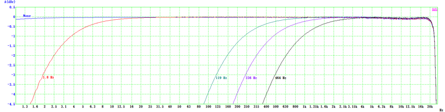
Frequency Response of Built-in High Pass Filter (sampled at 48 kHz)
5. Examples
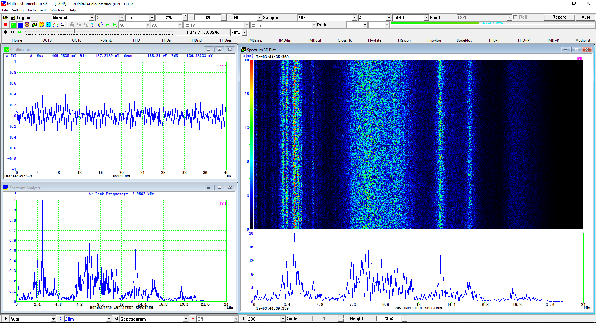
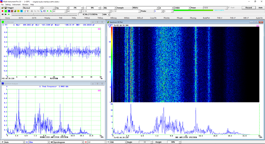
(1) VT IEPE-2G05 with Multi-Instrument Pro + Spectrum 3D Plot
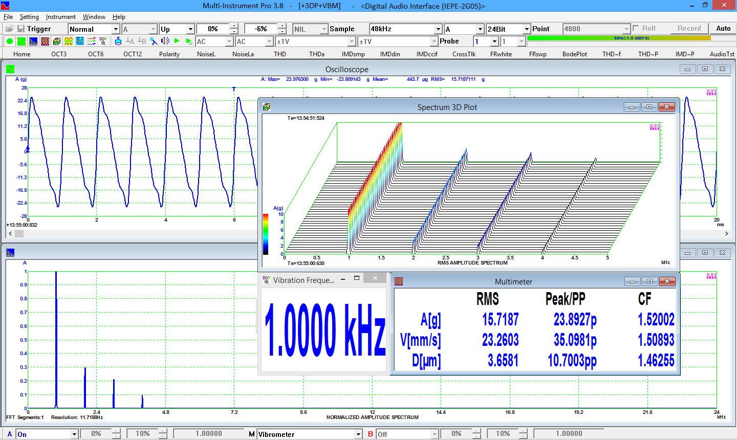
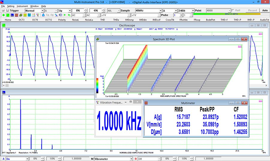
(2) VT IEPE-2G05 with Multi-Instrument Pro + Spectrum 3D Plot + Vibrometer
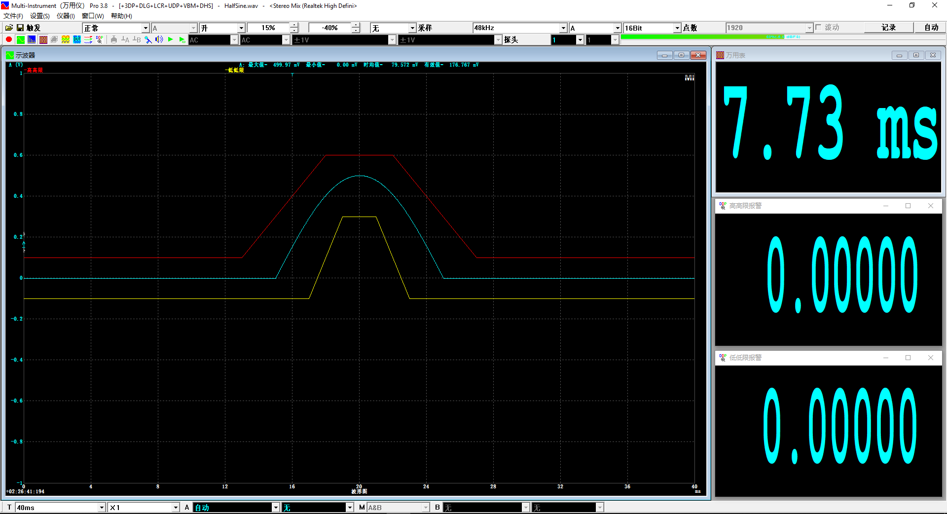
(3) Half-sine Shock Test (Video:
ShockTestWithMulti-Instrument.mp4 )

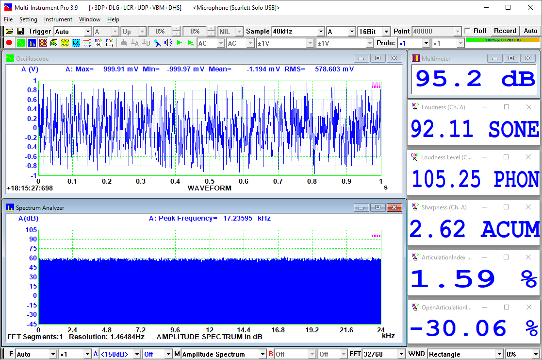
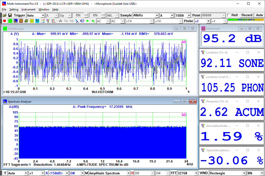
(4) Sound Quality Measurement
dBSPL, Loudness,
Loudness Level, Sharpness, Articulation Index and Open Articulation
Index of a white noise in a Free Field with an IEPE Measurement Microphone
(Note: Multi-Instrument Pro or above is required)
(5) Five Types of Shock Response Spectrum of a Half-sine Pulse
(Note: Multi-Instrument Pro or above is required)
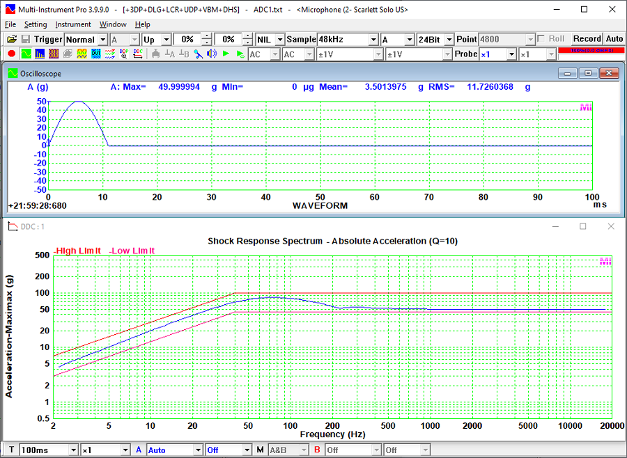
Absolute Acceleration Shock Response Spectrum (Multi-Instrument Pro or
above is
required)
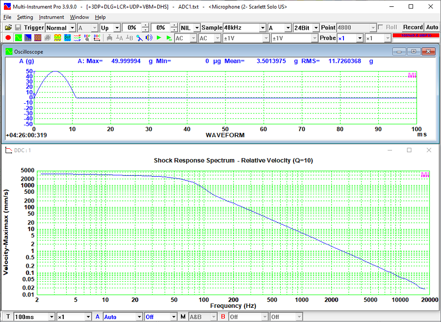
Relative Velocity Shock Response Spectrum (Multi-Instrument
Full Package is
required)
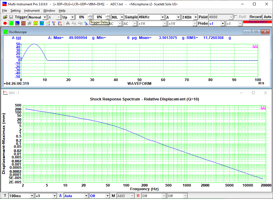
Relative Displacement Shock Response Spectrum (Multi-Instrument Full
Package is required)
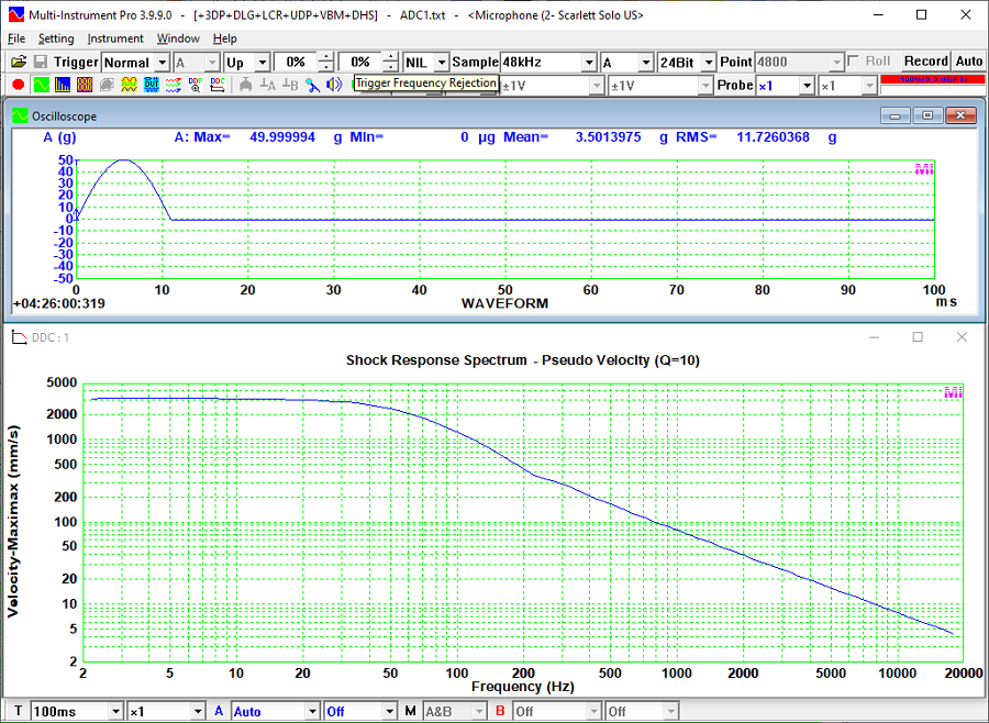
Pseudo
Velocity Shock Response Spectrum (Multi-Instrument Full Package is
required)
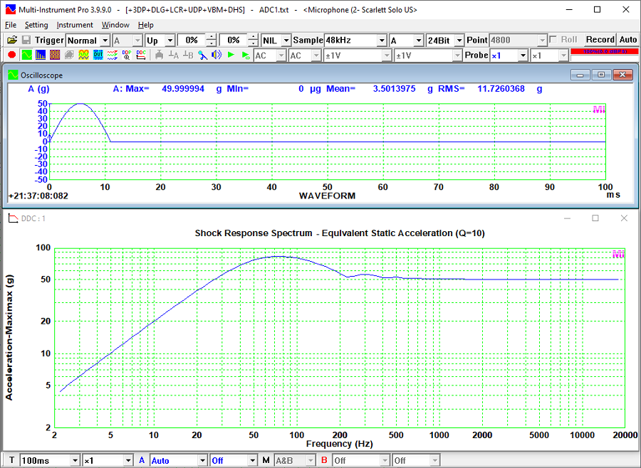
Equivalent Static Acceleration Shock Response Spectrum (Multi-Instrument
Full Package is
required)
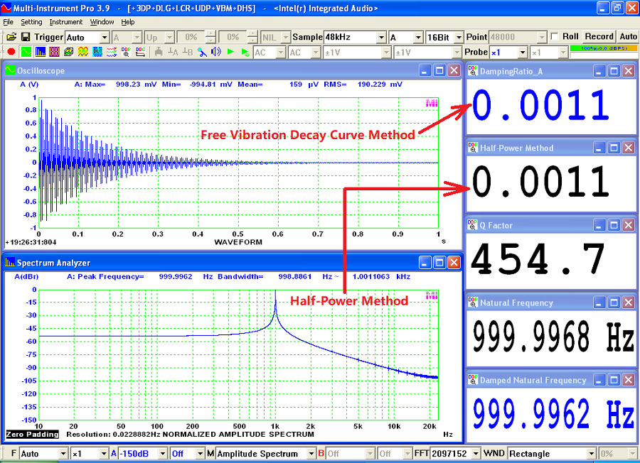
(6) Damping Ratio and Q factor Measurement using Free Vibration
Decay method and Half-Power method
(Note: Multi-Instrument Full Package is required)
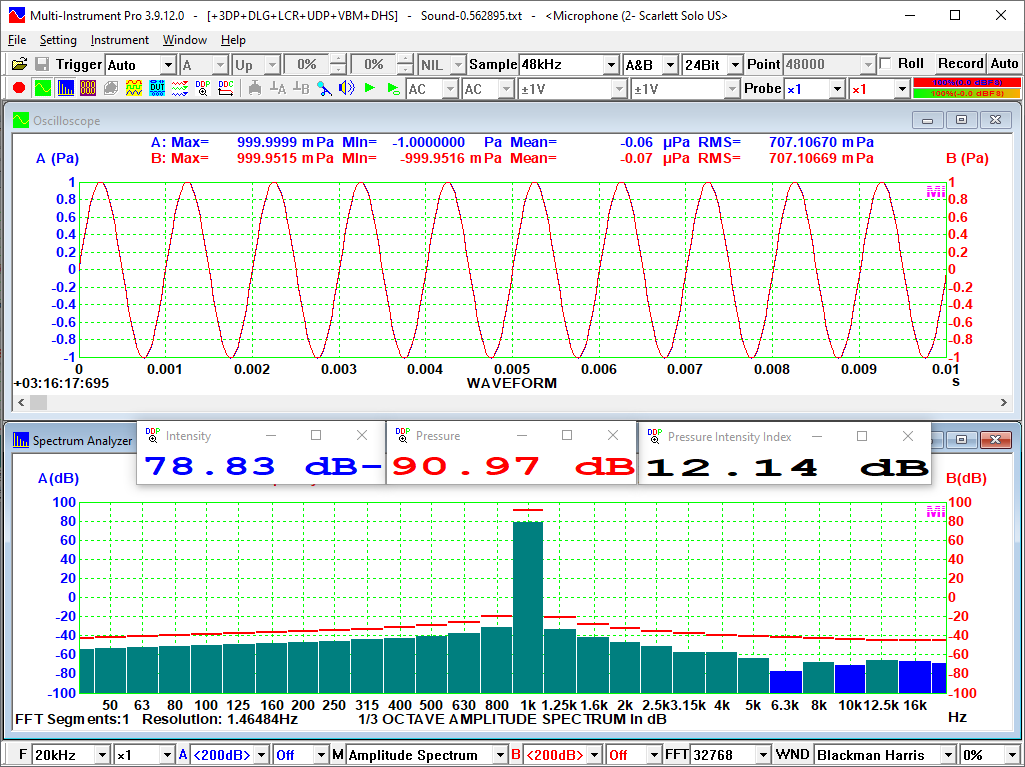
(7) Simultaneous Sound Intensity and Sound Pressure Measurement using a
P-P Sound Intensity Probe
(Note: Multi-Instrument Full Package is required)

|